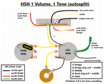

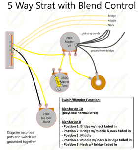
In addition to our coil split diagrams for both "modern" and the popular "50s" style wiring using push pull pots for volume controls, the below diagram shows how to do the same using tone push pull pots as the coil split switch.

This setup makes use of 2 x 500k DPDT push pull pots and requires 4 conductor wire pickups to function properly. This setup is exactly the same as used in our Les Paul coil split harness.
Wiring Guide
The below guide is a step by step installation process for our Les Paul Coil Split wiring kit
You will need:
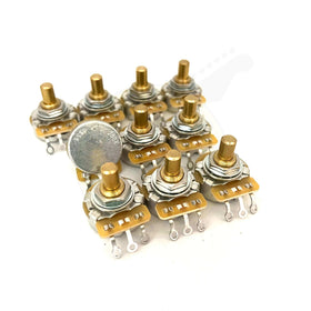
- 2 x CTS 500k push pull pots
- 2 x CTS 500k pots
- 1 x Switchcraft toggle switch
- 1 x Switchcraft jack socket
- 5ft Gavitt braided hook up wire
- 2 x 0.022uF capacitors
- Tinned copper wire
- Heat shrink tubing
All of the above components are available in our electronics section or as a complete wiring kit.
To make life easier and to prevent possible damage (either in the form of soldering iron burns or solderless splash) make a template to use for your soldering rather than doing it inside the tight Les Paul control cavity.
For this setup we are using the push pull pots and therefore having the coil splits as our tone controls.
Step One
Start off as usual by grounding the relevant lug on each volume pot. Our preferred method is to fill the eyelet with solder, bend it back onto the pot casing and re-heat the solder. The other method is to use a small off-cut of wire and solder this between the lug and the top of the pot casing.

The below photo is what you are aiming for - reheating the solder will create a bridge between the lug and the pot casing. This is a well grounded volume control. Repeat this process for both volume pots.

Step Two
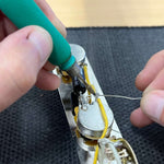
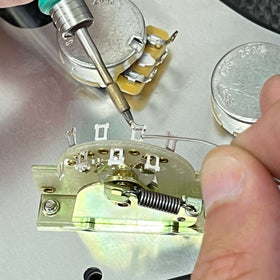
Moving onto the tone controls, there are two connections we need to make on each push pull pot - refer to the below photos.
To create the coil split itself, we need to ground one of the common lugs on the DPDT switch - in our example we ground hole C2 by soldering a jumper wire from C2 to the side of the pot casing.
The second connection, is for our tone control to work, we need to ground the output lug (middle) of the tone control to ground. Repeat this process for both push pull pots.

Step Three
Ground the four pots together using the tinned copper wire provided in the wiring kit. As CTS push pull pots have a plastic casing, you'll need to solder on the side of the pots instead.

Step Four
The final step on the controls harness itself is to solder in our capacitors. Our wiring kit comes with 0.022uF orange drops as standard but you can choose to upgrade to paper in oil too.
The capacitors get connected between the volume output (middle lug) and the third lug on the tone control.

Toggle Switch
Our wiring kit comes with braided hook up wire which is used to assemble the toggle switch.

The beauty of braided wire is that is works as two wires in one - the outer braid acts as our ground, and the inner cloth wire is the signal wire. The signal wire being surrounded by the ground offers superior shielding properties and much less noise/unwanted feedback - it is used for longer distances in circuits (ie - from toggle switch cavity to the main controls cavity)

Make sure you know what lug does what on the switch - refer to the below ground. Once completed, we will have three seperate lengths of braided wire which we will feed down the guitar towards the control cavity.

Follow the below photos to wire the switch.
Start off by connecting a length of tinned copper through the ground lug of the switch.

Next, solder a length of braided wire to each respective volume output lug and the third length of braided wire to the output lugs on the other side of the switch.

Finally, wrap the ground wire around all three braids and solder in place.

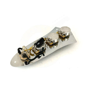
Installation
Time to connect everything together! Place the harness in the main control cavity and feed the three toggle switch wires in there too. Solder the main ground from the bridge (aka string ground) onto the most convenient pot - typically this is the volume pot.
The two volume output wires from the toggle switch get soldered to their respective output lugs on the volume pots. Solder the inner cloth wire to middle lug and solder the braid to ground. Refer to the below photos.

Pickups
For the pickups - you'll need 4 conductor lead wire humbuckers to finish the job. Colour codes vary from manufacturer so we will refer to the wires by name rather than colour (north start, north finish etc...)
Connect your pickup like this:
- North start (red in our photo) to the volume input lug.
- North finish (white) to hole "3" on the tone push pull
- South finish (green) to hole "3" on the tone push pull
- South start (black in our photo) to ground
- Bare wire to ground
The north finish and south finish wires can be twisted together and soldered as one into hole "3" on the push pull pot.
Likewise, the south start wire can be twisted with the bare wire and grounded together.

Connecting the jack socket
The third wire from our toggle switch runs all the way to the jack socket. It is recommended to cover this wire with heat shrink tubing as it runs through the main control cavity, just to ensure it doesn't touch anything it shouldn't and short out.
The jack socket has two lugs - one is the sleeve (ground) the other is the tip (signal). We need to solder our outer braid to the ground lug and the inner cloth wire to the signal lug.

Before you start, push a little 2cm length of tubing back up the main braid and out of the way for now - we will use this to cover the jack joint later.
Separate the braid from the inner cloth wire - twist the strands together and create a little braided tail.

Solder the inner cloth wire to the signal lug - then push the 2cm of heat shrink back down to cover the joint.

Finally, feed the braided tail through the ground lug and bend it back round before soldering in place.

You're all set! Plug in, play and split those coils!
Les Paul Wiring Diagrams
50s Les Paul Wiring (Refer to our guide on wiring a Les Paul)
3 Humbucker Les Paul (with push pull pot for middle pickup)
Coil Split Les Paul (modern wiring)
Coil Split Les Paul (50s wiring)
Les Paul/SG Junior (refer to our guide on wiring a Les Paul Junior)