
This guide will show you how to wire a Telecaster. The Telecaster was the first commercially produced guitar in the world. Way back in 1950, Leo Fender's first creation, the Esquire evolved into the Broadcaster in 1952 before finally settling on the Telecaster name. This guide is based on our Telecaster wiring kit and the components therein. There is a wiring diagram at the end of the article and we recommend you study it carefully before starting.
To wire a Telecaster, you will need;
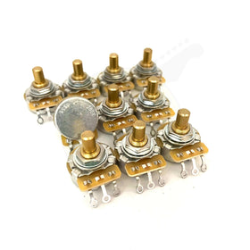
- 2 x CTS pots (250k solid shaft)
- 1 x 0.047uF capacitor
- 1 Switchcraft USA 1/4'' mono jack socket
- 1 x CRL 3 way Tele spring action switch
- Push back cloth wire
- Telecaster control plate
- Telecaster wiring diagram
- 3.2mm diameter heat shrink tubing (optional)
- Treble bypass capacitor (optional)
Preparation
- It is recommended that you lightly tin the terminals of the pots and switch that will require a solder connection, as well as the tips of the wires. Tinning the components before makes for an easier and more reliable solder connection - both electronically and mechanically.
- Ideally you want a temperature controlled soldering iron set to between 350°C-375°C (lead free will require the higher temperatures). Solder melts at substantially lower temperatures but you need to make sure the component gets hot enough to allow the solder to flow into the joint you are creating.
- Heat transfer is key - make sure to keep you solder tip clean and tinned throughout the process. Use a damp heat resistant sponge or brass/steel shavings to clean off excess solder and residue.
Step One - Assembly
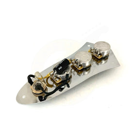
Assuming you have already removed the control plate from your guitar, assemble the components as per the below photo. The two CTS pots need to be facing each other. The pot nearest the switch is the volume control while the second pot is the tone control. With regards to the switch, it doesn't matter which way it sits in the control plate - it will work the same whichever way round you place it.

Step Two - Grounding & Capacitor
We'll start off by grounding - the third terminal of the volume pot needs to be grounded, this is what makes it function as a volume control.
Install the capacitor as per the below photos. One end of the capacitor needs to be soldered to the output (middle lug) of the tone control and the other end needs to go to ground. To do this, feed the capacitor lead through the volume lug eyelet and through to the back of the volume pot on the casing. Solder both points. This, installs our capacitor and grounds the volume control at the same time.


Once completed, it should look like the below photo.

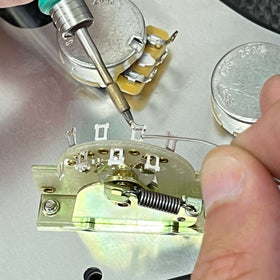
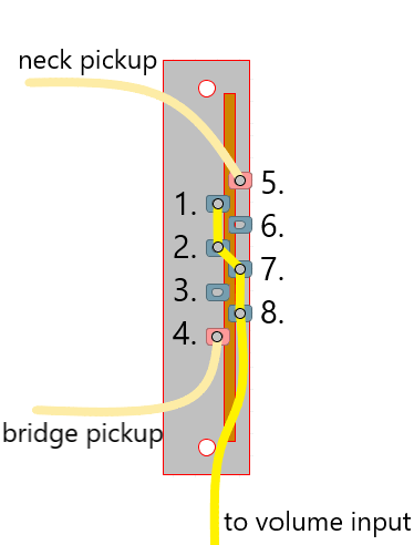
Step Three - Wiring a Telecaster Switch
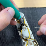
The easiest method is to use a single wire running from the top of the switch continuously to the input lug on the volume pot. Using the cream cloth wire provided, pull the cloth back 5cm or so until you have enough bare wire underneath. Follow the below 3 way switch wiring schematic and solder the end of the wire to the furthest switch terminal (lug 1 on the diagram), then lug 2, then 7 and finally 8.

The wire running from the switch gets connected to the input terminal of the volume pot - in the same eyelet you will solder the wire running to the terminal directly opposite on the tone control.

Step Four - Connecting the jack
Your Switchcraft jack has two terminals - a ground and a live/hot. Take 15cm of black cloth wire and solder it to the ground lug (the inner ring is always the ground on a jack). Once cooled, cover the joint with the heat shrink tubing. Not only does this create a more durable jack, it insulates and protects the joints from coming into contact with any shielding materials (copper foil, shielding paint etc...) that you may be using inside your guitar, potentially creating a short or grounding issues. Repeat this step using 20cm of yellow/cream wire for the hot terminal. You can also use this tubing to keep both of the jack's lead wires together until they break away to their different solder points in the circuit.

Thread the black wire through the ground lug (sleeve) and the yellow wire through the signal lug (tip). With both wires, ensure they have a true mechanical connection - bend the wire through and round so that the wire is in solid contact with both sides of the solder lug. Then solder it in place.

With the jack completed, solder the ground (black wire) to the back of the tone or volume control pot and the live (cream wire) to the output lug of the volume pot. This is the middle lug.

That's the initial harness completed. Let's move onto putting it in our guitar and connecting the pickups.
Step Five - Treble Bypass (Optional)
With our wiring kit, you can choose the optional treble bypass capacitor for the volume control. This comes pre-assembled and simply gets soldered across the input and the output of the volume control. Use the yellow heat shrink tubing provided to insulate the capacitor leads to prevent them shorting against the potentiometer casing.

Main Ground/String Ground
Make sure the guitar is grounded - typically, the main ground gets connected to the bridge (and therefore the strings). On a Telecaster, this is easily done by trapping the end of a ground wire underneath the bridge plate. The ground wire is held firmly in place when you screw the bridge back down onto the body.

Feed this wire through to the main control cavity and solder this to the top of the volume pot. That is our main ground done and if done properly, ensures your guitar is properly grounded. Both pickups need grounding too - so solder both pickup grounds to the top of the pot casing too. If your neck pickup has a separate ground wire for it's cover, this needs to be grounded too. Refer to the below photos.

Finally, connect the pickup hot/signal wires to the 3 way switch accordingly.

All done! Be careful not to trap any wires as you screw the control plate back down and watch out for any signal wires (or switch terminals) coming into contact with any shielding materials if you are using any.
Telecaster wiring is actually quite simple - as long as you are skilled enough with a soldering iron and have a good, clear and easy to read wiring diagram then you shouldn't have any problems at all.
This is the simple 3 way Telecaster wiring, the guitar's classical form but there are many other options to explore - Premier Guitar have a great guide on possible Telecaster wiring mods or we have a range of different wiring diagrams specifically suited for Telecaster wiring, including the 4 way mod, wiring in series as well as some vintage setups.
To wire a reverse Telecaster control plate so the 3 way switch is on the far side, (away from your hand) we have a wiring guide on how to do this.
All of the components used in this guide can be found in our guitar electronics section.

Telecaster Wiring diagrams
Wiring in Series (with push pull pot)
1 Single Coil, 1 Volume, 1 Tone
Telecaster 3 Way Switch Wiring
HS Telecaster Wiring (Humbucker/Single Coil)
Guitar Wiring Guides
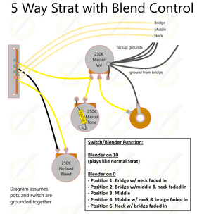
How to Wire a Strat with Blend Control